FAQ/ Manual Procedure for Calculating the Collapse Risk Zone
Please tell me the procedure for creating a house collapse risk zone (flooding) in accordance with the "Manual for Creating Flood Area Maps (4th Edition)" (Reference 6) using DioVISTA.
response
Below is an overview of the tasks we are considering.
Assumption: Assume that the normal flood calculation for the assumed maximum (L2) hydrograph has already been completed.
This section shows the procedure for calculating flooding when flooding at peak water level.
Step 1. Sets the porosity.
Set the porosity to 1 for the entire area. This is due to the following request:
Manual for Mapping Flooded Areas (4th Edition) p. 23
4.2. Setting the risk zone of house collapse due to flood flow
(2) Basic equations
The basic equation considers the risk of flood flow directly acting on buildings located in the shielding area due to the collapse of buildings on the embankment side, etc., and does not consider transmittance and porosity (transmittance and porosity are set to 100%). ...
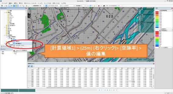
As shown in the figure below,[Calculation Area 1] operate > (right-click)[(25m)]>> [Porosity] [Editing Values] .
[Transmittance X] , [Transmittance Y] if specified, they also set 1 for the entire area.
If not specified,[Transmittance X] , [Transmittance Y] is [Porosity] created from and does not require editing.
Step 2. Set the roughness.
For roughness, set the value of open space / green space (0.025~0.05) or road (0.015~0.047) for the entire area. This is due to the following requests:
Manual for Mapping Flooded Areas (4th Edition) p. 23
4.2. Setting the risk zone of house collapse due to flood flow
(2) Basic equations
... Regarding the bottom roughness coefficient, an appropriate value shall be set, such as using the values of open space, green space, or road in Table 3.2-1.
The operation is the same as in Step 1 above.
Step 3. Gets the peak water level of a river.
Simulate all breaches by invalidating them.
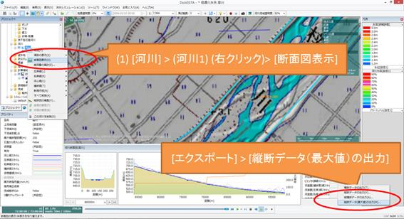
After the simulation ends, select > from the section view of the river[export] [Output of profile data (maximum value)] .
Step 4. Set the water level at the break.
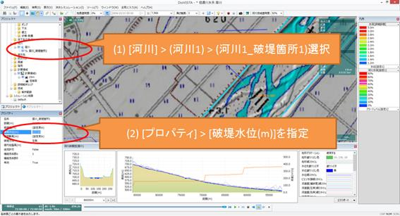
Specify the peak water level obtained in Step 3 above as the breach water level.
Step 5. Calculate the simulation.
Since only the house collapse risk zone (flooding) needs to be known, the calculation period can be short.
For example, ending the simulation one hour after the levee breaks will help reduce the calculation time.
Step 6. Create an envelope diagram of the maximum immersion depth.
[menu] Select [Flood simulation] > > [export] > [Export Maximum Envelope] .
Of the obtained netCDF files, MAXALL_TIME. The NC contains the House Collapse Zone (flood) flag (value 1).
Similarly, out of the resulting CSV file, DZONE. CSV contains the same data.
Replace these data with the results of the assumed maximum (L2) flood calculation that you have already created.
CSV file (DZONE.CSV) replaces the file.
MAXALL_TIME. NC opens NetCDF and replaces the value of the variable.
You can do this using netCDF tools such as nco, ncdump, ncgen, or by writing a program.
In addition, deliveries that include a house collapse risk zone are stored in DZONE. CSV and MAXALL_TIME. NC. For details, see "Guidelines for digitization of flood area map data (3rd edition)" Reference 34) p. 39 Table 3 "Elements included in each file".
DZONE. Since the CSV is only home collapse risk zone data, the results calculated in the collapse zone can be used as is.
MAXALL_TIME. For NC, the results calculated in L2 are also required because they contain data for maximum infusion depth, maximum flow velocity, and immersion duration.
Therefore, in addition to the results of the two simulation results (when the flood start water level is reached and when the peak water level is reached) calculated in Step1~5, it is considered necessary to output the three types of L2 calculation results using the export function of the maximum envelope.